INLET TEST CASE: Difference between revisions
No edit summary (change visibility) |
No edit summary (change visibility) |
||
| Line 1: | Line 1: | ||
<div class="title">Inlet Test Case</div> | <div class="title">Inlet Test Case</div> | ||
This | This test case couples ROMS and [[SWAN]] directly using the Modeling Coupling Toolkit (MCT) library. To run this application the user needs to activate [[Options#INLET_TEST|INLET_TEST]]. It only can be run in distributed-memory (MPI) since the parallel threads are split to run both ROMS and SWAN at the same time. This test illustrates the | ||
significance of wave-current coupling. This application and coupling methodology is described in [[Bibliography#WarnerJC_2008a|Warner ''et al.'' (2008)]]. | |||
This test case models and idealized tidal inlet system. The model domain is a 15x14 km rectangle with a uniform initial depth of 4 m. The model setup parameters are shown in the table below. The domain is separated into two regions: the seaward (top) and back-barrier (bottom) regions. The seaward region is open with radiation conditions on the western, northern and eastern edges. The back-barrier region is enclosed with four walls and is connected to the seaward region through a 2 km wide inlet. The model is forced by a tide and waves. An oscillating water level is imposed on the northern edge with a tidal amplitude of 1 m. Waves are also imposed on the northern edge with a height of 1 m, directed to the south with a period of 10s. | |||
Table 1. Important model parameters: | |||
Table 1. | |||
<wikitex> | <wikitex> | ||
{| border="1" cellspacing="0" cellpadding="5" align="center" | {| border="1" cellspacing="0" cellpadding="5" align="center" | ||
| Line 27: | Line 27: | ||
|- | |- | ||
|time step | |time step | ||
| | |[[Variable#dt|dt]] | ||
|10 s | |10 s | ||
|- | |- | ||
| Line 84: | Line 84: | ||
Below we provide a brief example of the model output. | Below we provide a brief example of the model output. | ||
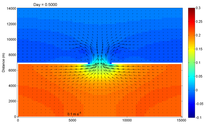
[[Image:Inlet_test_zeta_day0.5.png|thumb|850px|none|<center><b>Figure 1:</b> ROMS output of free surface and barotropic currents at t=0.5 days.</center>]] | |||
[[Image:Inlet_test_zeta_day0.5.png|thumb|850px|none|<center><b>Figure 1:</b> ROMS output of free surface and | |||
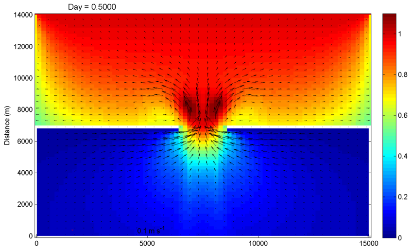
[[Image:Inlet_test_Hwave_day0.5.png|thumb|850px|none|<center><b>Figure 2:</b> SWAN output of wave height (Hwave, m) and | [[Image:Inlet_test_Hwave_day0.5.png|thumb|850px|none|<center><b>Figure 2:</b> SWAN output of wave height (Hwave, m) and barotropic currents.]] | ||
Revision as of 17:52, 29 October 2008
This test case couples ROMS and SWAN directly using the Modeling Coupling Toolkit (MCT) library. To run this application the user needs to activate INLET_TEST. It only can be run in distributed-memory (MPI) since the parallel threads are split to run both ROMS and SWAN at the same time. This test illustrates the significance of wave-current coupling. This application and coupling methodology is described in Warner et al. (2008).
This test case models and idealized tidal inlet system. The model domain is a 15x14 km rectangle with a uniform initial depth of 4 m. The model setup parameters are shown in the table below. The domain is separated into two regions: the seaward (top) and back-barrier (bottom) regions. The seaward region is open with radiation conditions on the western, northern and eastern edges. The back-barrier region is enclosed with four walls and is connected to the seaward region through a 2 km wide inlet. The model is forced by a tide and waves. An oscillating water level is imposed on the northern edge with a tidal amplitude of 1 m. Waves are also imposed on the northern edge with a height of 1 m, directed to the south with a period of 10s.
Table 1. Important model parameters:
<wikitex>
| Model Parameter | Variable | Value |
|---|---|---|
| length, width, depth | $Xsize$, $Esize$, $depth$ | 15000 m, 14000 m, 4.0 m |
| number of grid spacings | $Lm$, $Mm$, $Nm$ | 75, 70, 10 |
| bottom Roughness | $z_{ob}$ | 0.015 m |
| time step | dt | 10 s |
| simulation steps | $Ntimes$ | 17280 steps (2 days) |
| morphology factor | $morph\_fac$ | 10 (=20 day scaled simulation) |
| grain size | $sd50$ | 0.10 mm |
| settle velocity | $w_s$ | 11.0 mm s-1 |
| erosion rate | $E_o$ | 5 x 10⁻³ kg m-2s-1 |
| critical stress | $\tau_{cd}$, $\tau_{ce}$ | 0.10 Nm-2 |
| porosity | $\phi$ | 0.50 |
| bed thickness | $bed\_thick$ | 10.0 m |
| northern edge tide | $A$, $T_t$ | 1.0 m, 12 h |
| northern edge wave height | $H_{sig}$ | 2 m |
| northern edge wave period | $T$ | 10 s |
| northern edge wave direction | $\theta$ | from 0° (from North) |
</wikitex>
Below we provide a brief example of the model output.

