SED TEST1 CASE: Difference between revisions
No edit summary (change visibility) |
No edit summary (change visibility) |
||
| Line 73: | Line 73: | ||
—Simulation 2: Imposing a constant bed slope and water surface slope of 4x10⁻⁵ m/m. This simulation forced the water surface elevation and hence the bottom stress. Radiation boundary conditions were imposed for the depth-averaged velocity along with a clamped water surface condition at each boundary. The bed slope of 4x10⁻⁵ was selected to produce a depth-averaged velocity of 1m/s (similar to simulation 1) with a Z0 = 0.005. | —Simulation 2: Imposing a constant bed slope and water surface slope of 4x10⁻⁵ m/m. This simulation forced the water surface elevation and hence the bottom stress. Radiation boundary conditions were imposed for the depth-averaged velocity along with a clamped water surface condition at each boundary. The bed slope of 4x10⁻⁵ was selected to produce a depth-averaged velocity of 1m/s (similar to simulation 1) with a Z0 = 0.005. | ||
For both simulations, vertical mixing was parameterized using six different closure schemes: MY25, KKLpara, KKLmin, KE, KW88, and ANA | |||
MY25 = Mellor Yamada Level 2.5 Closure, parabolic wall proximity function | |||
KKLpara = Generic Length Scale parameterized as Mellor Yamada Level 2.5 with a parabolic wall proximity function | |||
KKLmin = Generic Length Scale parameterized as Mellor Yamada Level 2.5 with a linear wall proximity function (minimum distance to each surface) | |||
KE = Generic Length Scale parameterized as k-epsilon closure | |||
KW88 = Generic Length Scale parameterized as k-omega closure | |||
ANA = analytical expression of a parabolic vertical eddy diffusivity and viscosity profile: | |||
Kz = k u* z (1 - z/D) | |||
where Kz = vertical eddy viscosity, m²/s | |||
z = height above the bottom, m | |||
D = depth of flow, m, = 10 m | |||
and u* = friction velocity which was calculated according to the logarithmic profile. | |||
Revision as of 19:49, 7 April 2008
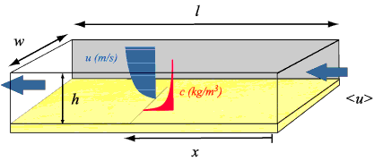
This case provides a fundamental check of the ability of a model to 1) represent a simple flow, 2) flux material from the bed, and 3) develop a suspended-sediment profile.
This case provides a fundamental check of the ability of a model to 1) represent a simple flow, 2) flux material from the bed, and 3) develop a suspended-sediment profile.

Model Parameters
The following parameters were used for the Suspended Sediment Test in Channel test case.
| Model Parameter | Variable | Value |
|---|---|---|
| length, width, depth | Xsize, Esize, depth | 10000 m, 100 m, 10 m |
| number of grid spacings | Lm, Mm, Nm | 100, 10, 20 (+variable) |
| bottom roughness | Zob | 0.0053 m |
| time step | dt | 30 s |
| simulation steps | Ntimes | 5000 |
| settle velocity | ws | 1.0 mm s-1 |
| erosion rate | E0 | 5x10⁻⁵ kg m-2 s-1 |
| critical stresses | τce | 0.05 N m-2 |
| porosity | ϕ | 0.90 |
| bed slope | S0 | 4x10⁻⁵ |
| Inflow/Outflow boundary condition | u | 1 m s-1 |
Channel Initial Conditions
Channel initial conditions: The test channel was modeled by establishing a grid parameterized with dx = 100 m , dy=100 m, f0 = 0, and h = 10 m (flat bottom). Initial conditions set a vertical logarithmic velocity profile for u (not required but provided reasonable starting values), v = 0, zeta (water surface height) = 0, SSC in the water column = 0, and bed thickness = 1 m (to provide unlimited supply). The model was forced with 2 methods :
—Simulation 1: Imposing a constant flow of 10 m³/s/m of width. This simulation allowed that water surface elevation to vary. Radiation boundary conditions were imposed for the water level along with a constant flow imposed by a depth averaged velocity ubar = 1.0 m/s at the upstream and downstream boundaries.
—Simulation 2: Imposing a constant bed slope and water surface slope of 4x10⁻⁵ m/m. This simulation forced the water surface elevation and hence the bottom stress. Radiation boundary conditions were imposed for the depth-averaged velocity along with a clamped water surface condition at each boundary. The bed slope of 4x10⁻⁵ was selected to produce a depth-averaged velocity of 1m/s (similar to simulation 1) with a Z0 = 0.005.
For both simulations, vertical mixing was parameterized using six different closure schemes: MY25, KKLpara, KKLmin, KE, KW88, and ANA MY25 = Mellor Yamada Level 2.5 Closure, parabolic wall proximity function KKLpara = Generic Length Scale parameterized as Mellor Yamada Level 2.5 with a parabolic wall proximity function KKLmin = Generic Length Scale parameterized as Mellor Yamada Level 2.5 with a linear wall proximity function (minimum distance to each surface) KE = Generic Length Scale parameterized as k-epsilon closure KW88 = Generic Length Scale parameterized as k-omega closure ANA = analytical expression of a parabolic vertical eddy diffusivity and viscosity profile:
Kz = k u* z (1 - z/D) where Kz = vertical eddy viscosity, m²/s z = height above the bottom, m D = depth of flow, m, = 10 m and u* = friction velocity which was calculated according to the logarithmic profile.