Numerical Solution Technique
Horizontal Discretization
<wikitex> In the horizontal, the ROMS governing equations are discretized over a boundary-fitted, orthogonal curvilinear coordinates ($\xi$, $\eta$) grid. The general formulation of the curvilinear coordinates system allows Cartesian, polar and spherical coordinates applications. The transformation of any of these coordinates to ROMS ($\xi$, $\eta$) grid is specified in the metric terms (pm, pn).
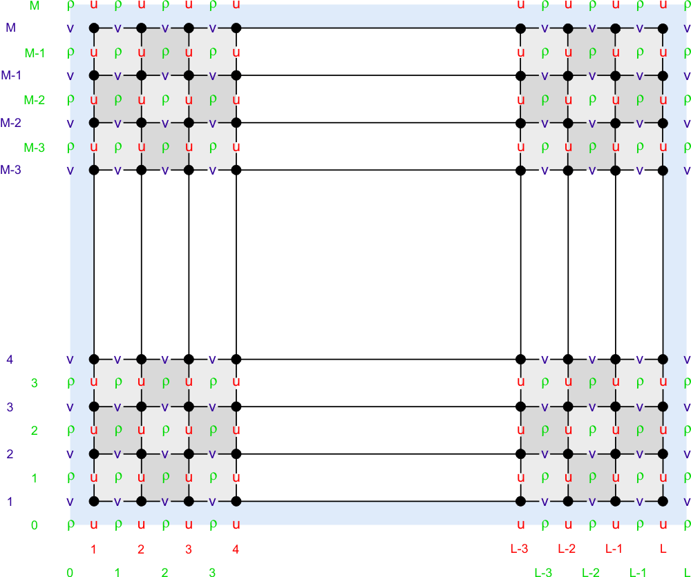
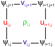
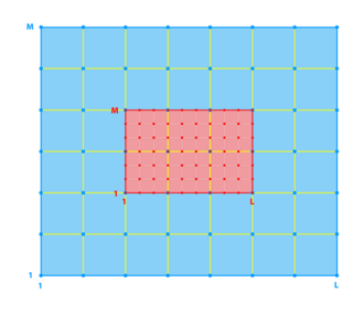
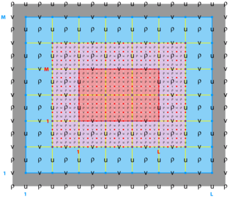
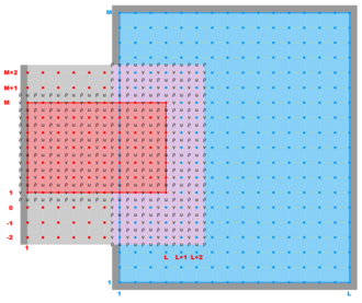
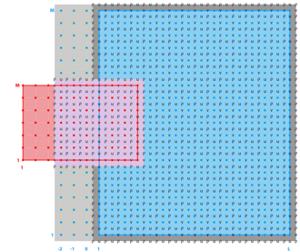
The model state variables are staggered using an Arakawa C-grid. As illustrated below, the free-surface (zeta), density (rho), and active/passive tracers (t) are located at the center of the cell whereas the horizontal velocity (u and v) are located at the west/east and south/north edges of the cell, respectively. That is, the density is evaluated between points where the currents are evaluated.
In ROMS all the state arrays are dimensioned the same size to facilitate parallelization. However, the computational ranges for all the state variables are:
| Variable | Interior Range | Full Range |
|---|---|---|
| $\rho$-type | 1:Lm(ng),1:Mm(ng) | 0:L(ng),0:M(ng) |
| $\psi$-type | 2:Lm(ng),2:Mm(ng) | 1:L(ng),1:M(ng) |
| u-type | 2:Lm(ng),1:Mm(ng) | 1:L(ng),0:M(ng) |
| v-type | 1:Lm(ng),2:Mm(ng) | 0:L(ng),1:M(ng) |
</wikitex>
Coastal boundaries can also be specified as a finite-discretized grid via land/sea masking arrays (rmask, umask, and vmask).
Vertical Discretization
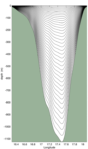
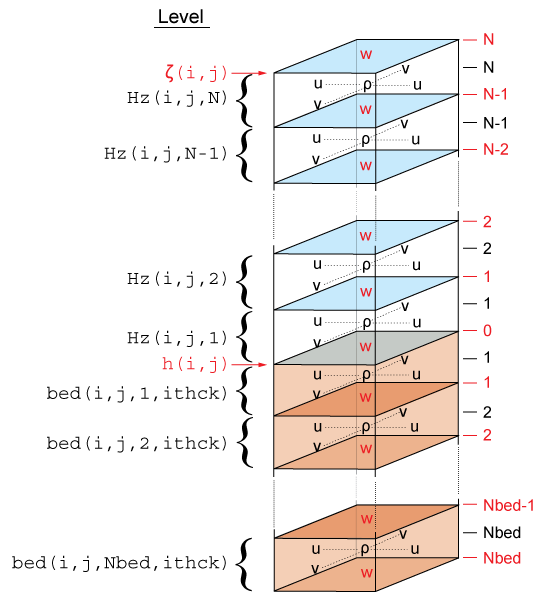
<wikitex> The ROMS governing equations are discretized over variable topography using a stretched, terrain-following, vertical coordinate. As a result, each grid cell may have different level thickness (Hz) and volume. The model state variables are vertically staggered so that horizontal momentum (u, v), (rho), and active/passive tracers (t) are located at the center of the grid cell. The vertical velocity (omega, w) and vertical mixing variables (Akt, Akv, etc) are located at the bottom and top faces of cell. See diagram below.
The total thickness of the water column is $\zeta(i,j)+h(i,j)$. The bathymetry (h) is usually time invariant whereas the free-surface (zeta) evolves in time. However, in sediment applications h changes with time when SED_MORPH is activated. At input and output, the bathymetry is always a positive quantity. However, the depths z_r(i,j,k) and z_w(i,j,k) are negative for all locations below the mean sea level.
</wikitex>
Masking of Land Areas
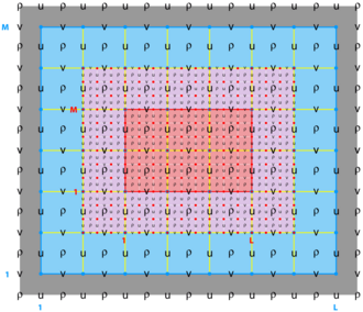
<wikitex> ROMS has the ability to work with interior land areas, although the computations occur over the entire model domain. The grid structure as a whole is shown above while two land cells are shown here:
The process of defining which areas are to be masked happens during the preparation of the grid file, while this section describes how the masking affects the computation of the various terms in the equations of motion. </wikitex>
Velocity points
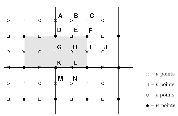
<wikitex> At the end of every timestep, the values of many variables within the masked region are set to zero by multiplying by the mask for either the $u$, $v$ or $\rho$ points. This is appropriate for the $v$ points E and L in the figure, since the flow in and out of the land should be zero. It is likewise appropriate for the $u$ point at I, but is not necessarily correct for point G. The only term in the $u$ equation that requires the $u$ value at point G is the horizontal viscosity, which has a term of the form ${\partial \over \partial \eta} \nu {\partial u \over \partial \eta}$. Since point G is used in this term by both points A and M, it is not sufficient to replace its value with that of the image point for A. Instead, the term ${\partial u \over \partial \eta}$ is computed and the values at points D and K are replaced with the values appropriate for either free-slip or no-slip boundary conditions. Likewise, the term ${\partial \over \partial \xi} \nu {\partial v \over \partial \xi}$ in the $v$ equation must be corrected at the mask boundaries.
This is accomplished by having a fourth mask array defined at the $\psi$ points, in which the values are set to be no-slip in metrics.F. For no-slip boundaries, we count on the values inside the land (point G) having been zeroed out. For point D, the image point at G should contain minus the value of $u$ at point A. The desired value of ${\partial u \over \partial \eta}$ is therefore $2 u_{\bf A}$ while instead we have simply $u_{\bf A}$. In order to achieve the correct result, we multiply by a mask which contains the value 2 at point D. It also contains a 2 at point K so that ${\partial u \over \partial \eta}$ there will acquire the desired value of $-2 u_{\bf M}$. The corner point F is set to have a value of 1. </wikitex>
Temperature, Salinity and Surface Elevation
<wikitex> The handling of masks by the temperature, salinity and surface elevation equations is similar to that in the momentum equations, and is in fact simpler. Values of $T$, $S$ and $\zeta$ inside the land masks, such as point H in the figure above, are set to zero after every timestep. This point would be used by the horizontal diffusion term for points B, J, and N. This is handled by setting the first derivative terms at points E, I, and L to zero, to be consistent with a no-flux boundary condition. Note that the equation of state must be able to handle $T = S = 0$ since this is the value inside masked regions.
Wetting and Drying
There is now an option to have wetting and drying in the model, in which a cell can switch between being wet or being dry as the tides come in and go out, for instance. Cells which are masked out as above are never allowed to be wet, however.
- In the case of wetting and drying, a critical depth, $D_{crit}$, is supplied by the user.
- The total water depth ($D=h+\zeta$) is compared to $D_{crit}$. If the water level is less than this depth, no flux is allowed out of that cell. Water can always flow in and resubmerge the cell.
- The wetting and drying only happens during the 2-D computations; the 3-D computations see a depth of $D_{crit}$ in the "dry" areas.
</wikitex>
Nesting Grids
<wikitex> ROMS has a nested design structure for the temporal coupling between a hierarchy of parent and child grids. All the state model variables are dynamically allocated and passed as arguments to the computational routines via Fortran-90 dereferenced pointer structures. All private arrays are automatic; their size is determined when the procedure is entered. This code structure facilitates computations over nested grids of different topologies. There are three types of nesting capabilities in ROMS:
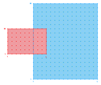
- Refinement Grids which provide increased resolution (3:1 or 5:1) in a specific region,
- Mosaics Grids which connect several grids along their edges, and
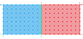
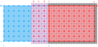
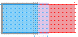
- Composite Grids which allow overlap regions of aligned and non-aligned grids.
</wikitex>
Refinement Grids
<wikitex>
</wikitex>
Mosaic Grids
<wikitex>
</wikitex>
Composite Grids
<wikitex>
</wikitex>
Time-Stepping Overview
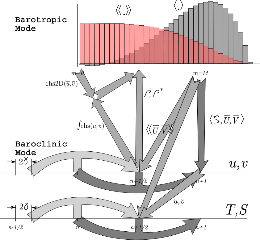
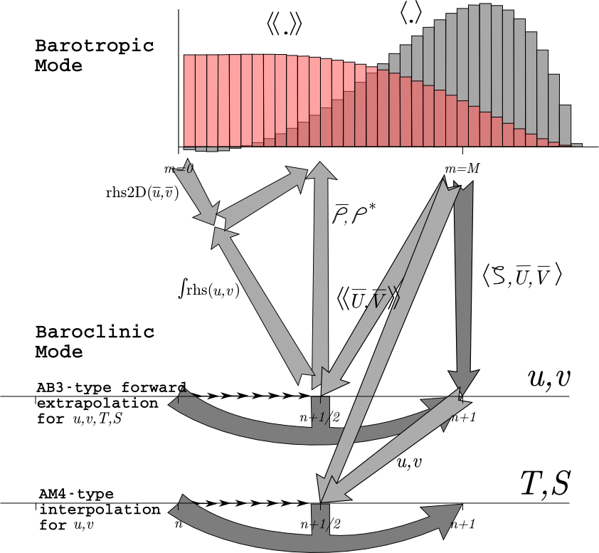
<wikitex> While time-stepping the model, we have a stored history of the model fields at time $n-1$, an estimate of the fields at the current time $n$, and we need to come up with an estimate for time $n+1$. For reasons of efficiency, we choose to use a split-explicit time-step, integrating the depth-integrated equations with a shorter time-step than the full 3-D equations. There is an integer ratio $M$ between the time-steps. The exact details of how the time-stepping is done varies from one version of ROMS to the next, with the east coast ROMS described here being older than other branches. Still, most versions have these steps:
- Take a predictor step for at least the 3-D tracers to time $n+1/2$.
- Compute $\overline{\rho}$ and $\rho^*$ for use in the depth-integrated time-steps, from the density either at time $n$ or time $n+1/2$.
- Depth integrate the 3-D momentum right-hand side terms at time $n+1/2$ for use in the depth-integrated time-steps (or extrapolate to obtain an estimate of those terms).
- Take all the depth-integrated steps. Store weighted time-means of the $\overline{u}$, $\overline{v}$ fields centered at both time $n+1/2$ and time $n+1$ (plus $\zeta$ at time $n+1$). The latter requires this time-stepping to extend past time $n+1$, using $M^*$ steps rather than just $M$.
- Use the weighted time-means from depth-integrated fields to complete the corrector step for the 3-D fields to time $n+1$.
Great care is taken to avoid the introduction of a mode-splitting instability due to the use of shorter time steps for the depth-integrated computations.
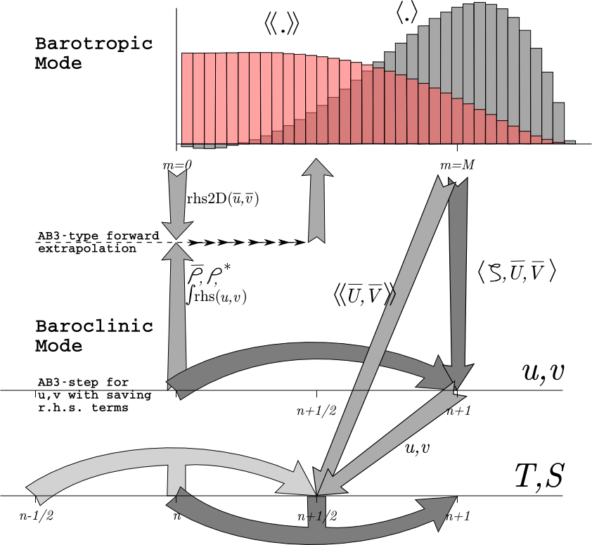
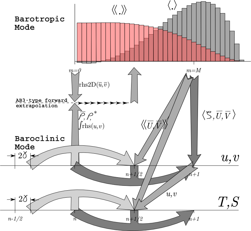
The mode coupling has evolved through the various ROMS versions, as shown in the figures below [from Shchepetkin and McWilliams (2008a)]. The time-stepping schemes are also listed in the following table and described in detail in Shchepetkin and McWilliams (2005) and Shchepetkin and McWilliams (2008b); the relevant ones are described in Time-stepping Schemes.
The following figures show the time-stepping and mode coupling used in the various ROMS versions. In all, the curved arrows update the 3-D fields; those with "pillars" are leapfrog in nature with the pillar representing the r.h.s. terms. Straight arrows indicate exchange between the barotropic and baroclinic modes. The shape functions for the fast time steps show just one option out of many possibilities. The grey function has weights to produce an estimate at time $n+1$, while the light red function has weights to produce an estimate at time $n+1/2$.
Timestepping table from Shchepetkin and McWilliams (2008a):
Conservation Properties
<wikitex> From Shchepetkin and McWilliams (2005), we have a tracer concentration equation in advective form: $$\frac{\partial C}{\partial t} + (u \cdot \nabla) C = 0 \eqno{(1)}$$ and also a tracer concentration equation in conservation form: $$\frac{\partial C}{\partial t} + \nabla \cdot (u C) = 0. \eqno{(2)}$$ The continuity equation: $$( \nabla \cdot u) = 0 \eqno{(3)}$$ can be used to get from one tracer equation to the other. As a consequence of eq. (1), if the tracer is spatially uniform, it will remain so regardless of the velocity field (constancy preservation). On the other hand, as a consequence of (2), the volume integral of the tracer concentration is conserved in the absence of internal sources and fluxes through the boundary. Both properties are valuable and should be retained when constructing numerical ocean models.
The semi-discrete form of the tracer equation is: $$ \eqalign{ {\partial \over \partial t} \left( {H_z C \over m n} \right) &+ \delta_{\xi} \left( {u \overline{H_z}^\xi \overline{C}^\xi \over \overline{n}^\xi} \right) + \delta_{\eta} \left( {v \overline{H_z}^\eta \overline{C}^\eta \over \overline{m}^\eta} \right) + \delta_\sigma \left( \overline{C}^\sigma {H_z \Omega \over m n} \right) =\cr &{ 1 \over mn} {\partial \over \partial \sigma} \left( {K_m \over \Delta z} {\partial C \over \partial \sigma} \right) + {\cal D}_C + {\cal F}_C} \eqno{(4)}$$
Here $\delta_{\xi}$, $\delta_{\eta}$ and $\delta_\sigma$ denote simple centered finite-difference approximations to $\partial / \partial \xi$, $\partial / \partial \eta$ and $\partial / \partial \sigma$ with the differences taken over the distances $\Delta\xi$, $\Delta\eta$ and $\Delta \sigma$, respectively. $\Delta z$ is the vertical distance from one $\rho$ point to another. $\overline{ ( \qquad )}^{\xi}$, $\overline{ ( \qquad )}^{\eta}$ and $\overline{ ( \qquad)}^\sigma$ represent averages taken over the distances $\Delta\xi$, $\Delta \eta$ and $\Delta \sigma$.
The finite volume version of the same equation is no different, except that a quantity $C$ is defined as the volume-averaged concentration over the grid box $\Delta V$: $$ C = \frac{mn}{H_z} \int_{\Delta V} \frac{H_z C}{mn} \delta \xi
\, \delta \eta \, \delta \sigma$$
The quantity $\left(\frac{u \overline{H_z}^\xi \overline{C}^\xi}{\overline{n}^\xi} \right)$ is the flux through an interface between adjacent grid boxes.
This method of averaging was chosen because it internally conserves first moments in the model domain, although it is still possible to exchange mass and energy through the open boundaries. The method is similar to that used in Arakawa and Lamb; though their scheme also conserves enstrophy. Instead, we will focus on (nearly) retaining constancy preservation while coupling the barotropic (depth-integrated) equations and the baroclinic equations.
The timestep in eq. (4) is assumed to be from time $n$ to time $n+1$, with the other terms being evaluated at time $n+1/2$ for second-order accuracy. Setting $C$ to 1 everywhere reduces eq. (4) to: $$\frac{\partial}{\partial t} \left( \frac{H_z}{m n} \right)
  + \delta_{\xi} \left(
  \frac{u \overline{H_z}^\xi }{\overline{n}^\xi} \right)
  + \delta_{\eta} \left(
  \frac{v \overline{H_z}^\eta}{\overline{m}^\eta} \right)
  + \delta_\sigma \left(
  \frac{H_z \Omega}{m n} \right) = 0 \eqno{(5)}$$
If this equation holds true for the step from time $n$ to time $n+1$, then constancy preservation will hold.
In a hydrostatic model such as ROMS, the discrete continuity equation is needed to compute vertical velocity rather than grid-box volume $\frac{H_z}{m n}$ (the latter is controlled by changes in $\zeta$ in the barotropic mode computations). Here, $\frac{H_z \Omega}{m n}$ is the finite-volume flux across the \em{moving} grid-box interface, vertically on the $w$ grid.
The vertical integral of the continuity equation (5), using the vertical boundary conditions on $\Omega$, is: $$ \frac{\partial}{\partial t} \left( \frac{\zeta}{mn} \right) +
  \delta_{\xi} \left(
  \frac{\overline{u} \overline{D}^\xi }{\overline{n}^\xi} \right)
  + \delta_{\eta} \left(
  \frac{\overline{v} \overline{D}^\eta}{\overline{m}^\eta} \right)
  = 0 \eqno{(6)}$$
where $\zeta$ is the surface elevation, $D= h+\zeta$ is the total depth, and $\overline{u},\overline{v}$ are the depth-integrated horizontal velocities. This equation and the corresponding 2-D momentum equations are timestepped on a shorter timestep than eq. (4) and the other 3-D equations. Due to the details in the mode coupling, it is only possible to maintain constancy preservation to the accuracy of the barotropic timesteps.
</wikitex>
Horizontal and Vertical Advection
<wikitex></wikitex>
Pressure Gradient
<wikitex></wikitex>
| SCRUM 3.0 | Rutgers | AGRIF | UCLA | Non-hydrostatic | |
|---|---|---|---|---|---|
| barotropic
mode |
LF-TR | LF-AM3 with FB
feedback |
LF-AM3 with FB
feedback$\dagger$ |
Gen. FB
(AB3-AM4) |
Gen. FB
(AB3-AM4) |
| 2-D $\alpha_{max}$, iter. | $\sqrt{2}$, (2)$\ddagger$ | 1.85, (2) | 1.85, (2) | 1.78, (1) | 1.78, (1) |
| 3-D momenta | AB3 | AB3 | LF-AM3 | LF-AM3 | AB3 (mod) |
| Tracers | AB3 | LF-TR | LF-AM3 | LF-AM3 | AB3 (mod) |
| internal
waves |
AB3 | Gen. FB
(AB3-TR) |
LF-AM3,
FB feedback |
LF-AM3,
FB feedback |
Gen. FB
(AB3-AM4) |
| $\alpha_{max}$, advect. | 0.72 | 0.72 | 1.587 | 1.587 | 0.78 |
| $\alpha_{max}$, Cor. | 0.72 | 0.72 | 1.587 | 1.587 | 0.78 |
| $\alpha_{max}$, int. w. | 0.72, (1) | 1.14, (1,2) | 1.85, (2) | 1.85, (2) | 1.78, (1) |
