Difference between revisions of "ESTUARY TEST CASE"
| (11 intermediate revisions by 3 users not shown) | |||
| Line 9: | Line 9: | ||
The domain is a long, narrow rectangular channel. | The domain is a long, narrow rectangular channel. | ||
{| border="1" | :{| border="1" | ||
!Model Parameter | !Model Parameter | ||
!Variable | !Variable | ||
| Line 15: | Line 15: | ||
|- | |- | ||
|Length (east-west) | |Length (east-west) | ||
|< | |align="center"|<span class="blue">l</span> | ||
|100000 m | |100000 m | ||
|- | |- | ||
|Width (north-south) | |Width (north-south) | ||
|< | |align="center"|<span class="blue">w</span> | ||
|1000 m | |1000 m | ||
|- | |- | ||
|Depth | |Depth | ||
|< | |align="center"|<span class="blue">h</span> | ||
|10 m at western end, decreasing linearly to 5 at eastern end | |10 m at western end, decreasing linearly to 5 at eastern end | ||
|- | |- | ||
|Temperature | |Temperature | ||
|< | |align="center"|<span class="blue">T</span> | ||
| | |10°C | ||
|} | |} | ||
| Line 35: | Line 35: | ||
Single grain size on bottom: | Single grain size on bottom: | ||
{| border="1" | :{| border="1" | ||
!Model Parameter | !Model Parameter | ||
!Variable | !Variable | ||
| Line 41: | Line 41: | ||
|- | |- | ||
|Size | |Size | ||
|< | |align="center"|<span class="blue">D<sub>50</sub></span> | ||
|0.15 mm | |0.15 mm | ||
|- | |- | ||
|Density | |Density | ||
|< | |align="center"|<span class="blue">ρ<sub>s</sub></span> | ||
| | |2650 kg/m<sup>3</sup> | ||
|- | |- | ||
|Settling Velocity | |Settling Velocity | ||
|< | |align="center"|<span class="blue">w<sub>s</sub></span> | ||
|0.50 mm/s | |0.50 mm/s | ||
|- | |- | ||
|Critical shear stress | |Critical shear stress | ||
|< | |align="center"|<span class="blue">τ<sub>c</sub></span> | ||
| | |0.05 N/m<sup>2</sup> | ||
|- | |- | ||
|Porosity | |Porosity | ||
|< | |align="center"|<span class="blue">φ</span> | ||
|0.90 | |0.90 | ||
|- | |- | ||
|Bed thickness | |Bed thickness | ||
|< | |align="center"|<span class="blue">bed_thick</span> | ||
| | |1 mm | ||
|} | |} | ||
| Line 74: | Line 74: | ||
==Initial Conditions== | ==Initial Conditions== | ||
Salinity distribution from west end = 35 to east end = 0. (Vertically well mixed) | Salinity distribution from <math>\color{green}{west\ end}\color{black}{=~35}</math> to <math>\color{green}{east\ end}\color{black}{=~0}</math>. (Vertically well mixed) | ||
==Boundary Conditions== | ==Boundary Conditions== | ||
General: | |||
North and south sides = walls with no fluxes, no friction | :'''North and south sides''' = walls with no fluxes, no friction | ||
Bottom roughness <math>K_{s} \ | :'''Bottom roughness''' <math>\color{blue}{K_{s}}\color{black}{~ =~ 0.15~ m~(}\color{blue}{Z_{o}}\color{black}{~ =~ }\color{blue}{K_{s}}\color{black}{/30~ =~ 0.005~ m )}</math> | ||
Sediment flux calculated by model | :'''Sediment flux''' = calculated by model | ||
Surface = free surface, no fluxes | :'''Surface''' = free surface, no fluxes | ||
Flow, Western end, tidal | Flow, Western end, tidal: | ||
<math>q_{west} \ | :<math>\color{blue}{q_{west}}\color{black}{~ =~ 4000~ m^{3}/s~ \times~ sin(}\color{blue}{\omega t}\color{black}{)~ -~}\color{blue}{q_{east}}</math> | ||
<math>\omega \ | :<math>\color{blue}{\omega}\color{black}{~ =~ 2\pi~ / }\color{blue}{T}</math> | ||
T = 12 | :<math>\color{blue}{T}\color{black}{~ =~ 12~ \times~ 3600~ seconds;~ t =~ model~ time~ step~,~ seconds~}</math> | ||
t = model time step, seconds< | |||
Flow, Eastern end, constant riverine (varying depth) | Flow, Eastern end, constant riverine (varying depth): | ||
<math>q_{east} \ | :<math>\color{blue}{q_{east}}\color{black}{~ =~ 400~ m^{3}/s}</math> | ||
Salinity, western end | |||
Radiation condition with nudging, <math>t_{nudge} \ | Salinity, western end: | ||
Salinity at eastern end = 0< | :Radiation condition with nudging, <math>\color{blue}{t_{nudge}}\color{black}{~ =~ 3~ hours }</math> | ||
:Salinity at eastern end = <math>0</math> | |||
==Output (ASCII files suitable for plotting)== | ==Output (ASCII files suitable for plotting)== | ||
At t = 10 days (20 tidal cycles) | At <math>\color{blue}{t}\color{black}{~ =~ 10~ days~ (20~ tidal~ cycles)}</math>: | ||
Tidally averaged velocity field (average over last 2 tidal cycles) | :Tidally averaged velocity field (average over last 2 tidal cycles) | ||
Bed profile | :Bed profile | ||
Tidal-mean suspended sediment field | :Tidal-mean suspended sediment field | ||
==Physical Constants== | |||
Gravitational acceleration: <math>\color{blue}{g}\color{black}{~ =~ 9.81~ m/s^{2}}</math><br> | |||
Von Karman's constant: <math>\color{blue}{\kappa}\color{black}{~ =~ 0.41}</math><br> | |||
Dynamic viscosity (and minimum diffusivity): <math>\color{blue}{\nu}\color{black}{~ =~ 1e-6~ m^{2}/s}</math> | |||
'''Note:''' | {{note}}'''Note:''' If a model incorporates physical constants that differ from these, and/or automatically calculates some values specified here, please specify the values used. | ||
If a model incorporates physical constants that differ from these, and/or automatically calculates some values specified here, please specify the values used. | |||
==Results== | ==Results== | ||
| Line 115: | Line 115: | ||
[[Image:Fig1.gif|center|frame|'''Figure 1.''' Initial salinity distribution for estuary simulations.]] | [[Image:Fig1.gif|center|frame|'''Figure 1.''' Initial salinity distribution for estuary simulations.]] | ||
Model was initialized with a constant longitudinal salinity field as shown in Figure 1. Simulations were the calculated for 20 tidal cycles (10 days), after which time a quasi-steady state had been reached. Figure 2 shows the resulting salinity fields for 4 different closure methods near the end of 20 tidal cycles. The 4 different closures are: MY25, Generic Length Scale (GLS) as KKL, GLS as KE, and GLS as KW88. The MY25 closure is computed based on the classical scheme of Mellor/Yamada (1982), and the GLS closures are computed with the method of Umlauf and Burchard ( | Model was initialized with a constant longitudinal salinity field as shown in '''Figure 1'''. Simulations were the calculated for 20 tidal cycles (10 days), after which time a quasi-steady state had been reached. '''Figure 2''' shows the resulting salinity fields for 4 different closure methods near the end of 20 tidal cycles. The 4 different closures are: MY25, Generic Length Scale (GLS) as KKL, GLS as KE, and GLS as KW88. The MY25 closure is computed based on the classical scheme of [[Bibliography#MellorGL_1982a|Mellor/Yamada (1982)]], and the GLS closures are computed with the method of [[Bibliography#UmlaufL_2003a|Umlauf and Burchard (2003)]]. The main difference is in the length scale limitations. For the MY25 method, the length scale is only limited in the calculation of the stability functions, whereas for the GLS method the length scale is limited in the production, wall proximity function, and the stability functions. | ||
The MY25 closure does not develop a well defined surface mixed layer as with the closures computed with the GLS method. This is most likely due to the length scale limitation and the buoyancy parameter (E3 = 1.8). As discussed by Burchard (2001), a value of c3 ~ 2.5 (E3 ~ 5.0) provides a more realistic simulation of a wind induced surface mixed layer test experiment. | The MY25 closure does not develop a well defined surface mixed layer as with the closures computed with the GLS method. This is most likely due to the length scale limitation and the buoyancy parameter (E3 = 1.8). As discussed by [[Bibliography#BurchardH_2001a|Burchard (2001)]], a value of c3 ~ 2.5 (E3 ~ 5.0) provides a more realistic simulation of a wind induced surface mixed layer test experiment. | ||
[[Image:Estuary_4panel_salt.gif|center|frame|'''Figure 2.''' Initial salinity distribution for estuary simulations.]] | [[Image:Estuary_4panel_salt.gif|center|frame|'''Figure 2.''' Initial salinity distribution for estuary simulations.]] | ||
Latest revision as of 13:13, 17 May 2016
This test case provides a fundamental check of the ability of a model to represent 1) mixing processes typical of estuarine conditions, 2) resuspension, advection, and deposition for suspended-sediment transport, 3) temporal dynamics of upper bed layer, and 4) interaction of suspended-sediment and the bed.
Domain
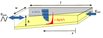
The domain is a long, narrow rectangular channel.
Model Parameter Variable Value Length (east-west) l 100000 m Width (north-south) w 1000 m Depth h 10 m at western end, decreasing linearly to 5 at eastern end Temperature T 10°C
Bottom Sediment
Single grain size on bottom:
Model Parameter Variable Value Size D50 0.15 mm Density ρs 2650 kg/m3 Settling Velocity ws 0.50 mm/s Critical shear stress τc 0.05 N/m2 Porosity φ 0.90 Bed thickness bed_thick 1 mm
Forcing
No Coriolis
No wind
No heating/cooling
Initial Conditions
Salinity distribution from to . (Vertically well mixed)
Boundary Conditions
General:
- North and south sides = walls with no fluxes, no friction
- Bottom roughness
- Sediment flux = calculated by model
- Surface = free surface, no fluxes
Flow, Western end, tidal:
Flow, Eastern end, constant riverine (varying depth):
Salinity, western end:
- Radiation condition with nudging,
- Salinity at eastern end =
Output (ASCII files suitable for plotting)
At :
- Tidally averaged velocity field (average over last 2 tidal cycles)
- Bed profile
- Tidal-mean suspended sediment field
Physical Constants
Gravitational acceleration:
Von Karman's constant:
Dynamic viscosity (and minimum diffusivity):
![]() Note: If a model incorporates physical constants that differ from these, and/or automatically calculates some values specified here, please specify the values used.
Note: If a model incorporates physical constants that differ from these, and/or automatically calculates some values specified here, please specify the values used.
Results
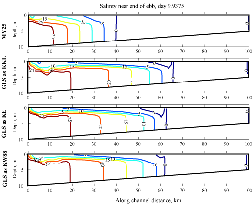
Model was initialized with a constant longitudinal salinity field as shown in Figure 1. Simulations were the calculated for 20 tidal cycles (10 days), after which time a quasi-steady state had been reached. Figure 2 shows the resulting salinity fields for 4 different closure methods near the end of 20 tidal cycles. The 4 different closures are: MY25, Generic Length Scale (GLS) as KKL, GLS as KE, and GLS as KW88. The MY25 closure is computed based on the classical scheme of Mellor/Yamada (1982), and the GLS closures are computed with the method of Umlauf and Burchard (2003). The main difference is in the length scale limitations. For the MY25 method, the length scale is only limited in the calculation of the stability functions, whereas for the GLS method the length scale is limited in the production, wall proximity function, and the stability functions.
The MY25 closure does not develop a well defined surface mixed layer as with the closures computed with the GLS method. This is most likely due to the length scale limitation and the buoyancy parameter (E3 = 1.8). As discussed by Burchard (2001), a value of c3 ~ 2.5 (E3 ~ 5.0) provides a more realistic simulation of a wind induced surface mixed layer test experiment.
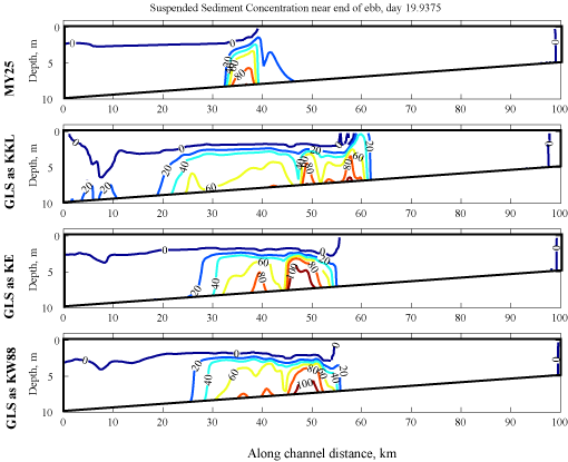
Suspended sediment results (figure 3) are very dependent on the bottom stresses and vertical mixing processes. For these simulations, a thin layer of sediment was placed on the bed at time = 10 days. Sediment parameters were selected to allow rapid erosion. Upstream riverine flow will transport the sediment downstream and the estuarine circulation creates a turbidity maximum at the limit of salt intrusion. For the MY25 closure, this limit is near x = 35 km, while for the KE and KW simulations, a near bottom turbidity maximum is located near x = 50 km. For the KKL simulation, the turbidity maximum is further upstream, near x = 60 km.


