Curvilinear Coordinates

Facts, news, and guidance about ROMS software

Moderators: arango, robertson

Post Reply
Message
Author
User avatar
arango
Site Admin
Posts: 1361
Joined: Wed Feb 26, 2003 4:41 pm
Location: DMCS, Rutgers University
Contact:

Curvilinear Coordinates

#1 Unread post by arango »

This is to remind you that ROMS/TOMS is formulated in general horizontal curvilinear coordinates. It is possible to formulate any application in Cartesian, spherical, or polar coordinates. You can activate a curvilnear application by turning on CPP option CURVILINEAR. Curvilinear applications include extra terms in the advection and any vector or tensor needs to be rotated to model generic coordinates (XI,ETA).

In curvilinear applications, the coordinate rotation angle is found in the ROMS grid and history NetCDF files. See NetCDF variable angle. It is defined as the counterclockwise angle (radians) between the XI-axis and true EAST at RHO-points.

Therefore, to transform between (XI,ETA) coordinates to (LON,LAT) coordinates, vectors and tensors need to be rotated according to

Code: Select all

u(LON,LAT)=u(XI,ETA)*cos(angle(i,j))-v(XI,ETA)*sin(angle(i,j))
v(LON,LAT)=v(XI,ETA)*cos(angle(i,j))+u(XI,ETA)*sin(angle(i,j))
conversely,

Code: Select all

u(XI,ETA)=u(LON,LAT)*cos(angle(i,j))+v(LON,LAT)*sin(angle(i,j))
v(XI,ETA)=v(LON,LAT)*cos(angle(i,j))-u(LON,LAT)*sin(angle(i,j))
Then, you need to consider that ROMS uses a staggered C-grid. That is, the vector components are not located in the same place:

Code: Select all

                ------- V(i,j+1)-------
                |                     |
             U(i,j)     RHO(i,j)   U(i+1,j)
                |                     |
                -------- V(i,j)--------
If plotting, you have two choices:

1) Draw vectors at PSI-points (cell's corners):

Code: Select all

 
          Upsi(i,j) = 0.5 * ( U(i,j-1) + U(i,j) )
          Vpsi(i,j) = 0.5 * ( V(i-1,j) + V(i,j) )
2) Draw vectors at interior RHO-points (cell's center):

Code: Select all

           Urho(i,j) = 0.5 * ( U(i,j) + U(i+1,j) )
           Vrho(i,j) = 0.5 * ( V(i,j) + V(i,j+1) )
It is more physical to draw vectors at PSI-points. It will be consistent with the physical boundaries of the domain. It will also show the behavior around Land/Sea masking, if any.

Now, the actual world is assumed to be at RHO-points. This will allow a well posed interpolation of vectors/tensors to C-grid locations. For instance, if you are providing wind components (Uwind,Vwind) to ROMS, they must be at RHO-points. So we can use the rotation angle to convert from (LON,LAT) to (XI,ETA) or viceversa.

ROMS assumes that all the input vectors are already in (XI,ETA)coordinates. At output ROMS, writes vectors in (XI,ETA) coordinates at the appropriate C-grid location. To visualize vectors the User needs to interpolate to either PSI- or RHO-locations and rotate back to (LON,LAT) coordinates, using above formulas.
Last edited by arango on Fri Apr 07, 2006 6:53 pm, edited 1 time in total.

kbrink
Posts: 1
Joined: Fri Oct 28, 2005 9:09 pm
Location: Woods Hole Oceanographic Institution

Curvilinear grid errors

#2 Unread post by kbrink »

I have been using the "SeaGrid" matlab code to generate a curvilinear grid, and it always returns a field of departure from orthogonality. I am wondering what sort of maximum departure is "good enough". After some web surfing, the only thing I have found is an exchange on the POM FAQ web site suggesting that this is not too big a problem.

Can someone point me to an appropriate reference or handy criterion on this?

User avatar
arango
Site Admin
Posts: 1361
Joined: Wed Feb 26, 2003 4:41 pm
Location: DMCS, Rutgers University
Contact:

#3 Unread post by arango »

Well, this is a good question. Unfortunately, it depens on the application resolution and coastal topology. Personally, I always try to avoid big grid distorsions and I keep the orthogonality about 95 percent or better. Is it also important to keep the grid aspect ratio (dx/dy) as close to one as possible. The important issue here is that the solution should be independent of grid topology.

Nowadays, I try to avoid curvilinear grids. I prefer to rotate rectangles and use land/sea masking to define a coastline. This is still a curvilinear grid but the grid angle is near constant. Notice my emphasis on rectangles. I avoid having square applications at all cost. This is because many of us use matlab or similar software and is very easy to transpose the coordinates of a matrix. This is hard to detect in ROMS during reading because both Lm and Mm have the same value. I know of users transposing the Coriolis parameter to disastrous consequences.

Also notice that in boundary fitted coastlines there are usually big distortions on bays and very fine resolution on headlands. This kind of behavior is undesired in small coastal applications. I prefer to have land/sea masking instead.
Last edited by arango on Mon Mar 06, 2006 8:54 pm, edited 1 time in total.

User avatar
kate
Posts: 4091
Joined: Wed Jul 02, 2003 5:29 pm
Location: CFOS/UAF, USA

#4 Unread post by kate »

The Seagrid program only calls "rect" once while the Fortran version calls it more times. The errors should drop quite rapidly with each successive call, but you get to a point where the thing blows up if the starting errors are too small, so it's nice to be able to tune the number of calls to one less than "too many".

The circle test problem pitted a curvilinear circle against a staircase circle. The rectangularity errors didn't seem to be the limiting factor. Instead, it was the large dx in the "bays", as mentioned by Hernan. The staircases provide errors of their own, so there's no perfect solution as long as we're dealing with structured grids.

I'm not afraid of square grids - just debug your analysis code beforehand.

User avatar
wilkin
Posts: 920
Joined: Mon Apr 28, 2003 5:44 pm
Location: Rutgers University
Contact:

#5 Unread post by wilkin »

When generating orthogonal grids you should be careful to ensure the geometry of the boundaries you input is such that you input square corners. If not, there is nothing the boundary-fitting algorithm can do to make the cell in the corner orthogonal, and it will dominate the errors and propagate a lack of orthogonality to many neighbouring cells.
John Wilkin: DMCS Rutgers University
71 Dudley Rd, New Brunswick, NJ 08901-8521, USA. ph: 609-630-0559 jwilkin@rutgers.edu

User avatar
kate
Posts: 4091
Joined: Wed Jul 02, 2003 5:29 pm
Location: CFOS/UAF, USA

#6 Unread post by kate »

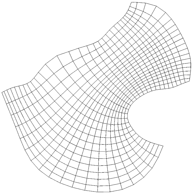
Here's an example grid:
Image
In this case, the corners in the NE are not orthogonal, leading to some orthogonality error there. However, I believe the larger errors are due to the resulting jump in dx along that NE wall. This drastic change in dx is not a good thing and probably leads to just as much trouble as steep bathymetry.

Here's one case where Seagrid might be better than the Fortran code - the boundary line you draw in Seagrid will be through the outisde rho image points. The grid is computed at fine resolution, leaving the largest errors outside the grid. The fortran code is expecting a boundary through the wall psi points, putting the largest errors inside the grid and copying them to the outside image points.

User avatar
m.hadfield
Posts: 521
Joined: Tue Jul 01, 2003 4:12 am
Location: NIWA

#7 Unread post by m.hadfield »

Well someone has to ask the obvious, naive question: What do these orthogonality errors look like in terms of flow distortion or whatever?

baipeng_up
Posts: 19
Joined: Mon Jul 22, 2013 4:54 am
Location: Ocean University of China

Re: Curvilinear Coordinates

#8 Unread post by baipeng_up »

I think may be the code for transforming real velocity to model velocity should be as follows, but I am not sure...

u(XI,ETA) = u(LON,LAT)*cos(angle(i,j))+v(LON,LAT)*sin(angle(i,j))
v(XI,ETA) = (u(LON,LAT)*sin(angle(i,j))-v(LON,LAT)*cos(angle(i,j)))*-1

User avatar
wilkin
Posts: 920
Joined: Mon Apr 28, 2003 5:44 pm
Location: Rutgers University
Contact:

Re: Curvilinear Coordinates

#9 Unread post by wilkin »

I do the angle rotation this way (in Matlab but you get the idea) using complex numbers. The reverse transformation (geographic to roms) just needs the opposite sign on the angle.

% rotate coordinates from roms xi,eta grid directions to geographic east,north
% (but only after averaging/interpolating u,v to the rho points)
uveitheta = (u_roms+1i*v_roms).*exp(1i*angle); % 1i = sqrt(-1) in Matlab
u_east = real(uveitheta);
v_north = imag(uveitheta);
John Wilkin: DMCS Rutgers University
71 Dudley Rd, New Brunswick, NJ 08901-8521, USA. ph: 609-630-0559 jwilkin@rutgers.edu

baipeng_up
Posts: 19
Joined: Mon Jul 22, 2013 4:54 am
Location: Ocean University of China

Re: Curvilinear Coordinates

#10 Unread post by baipeng_up »

wilkin wrote:I do the angle rotation this way (in Matlab but you get the idea) using complex numbers. The reverse transformation (geographic to roms) just needs the opposite sign on the angle.

% rotate coordinates from roms xi,eta grid directions to geographic east,north
% (but only after averaging/interpolating u,v to the rho points)
uveitheta = (u_roms+1i*v_roms).*exp(1i*angle); % 1i = sqrt(-1) in Matlab
u_east = real(uveitheta);
v_north = imag(uveitheta);
Appreciation for wilkin's reply! I use Matlab to prepare NC files for ROMS as you do, your code is very simple and clear and I'll recode my program following your idea.

Thanks again!

Serega.Osipov
Posts: 5
Joined: Thu Oct 01, 2015 4:41 am
Location: KAUST

Re: Curvilinear Coordinates

#11 Unread post by Serega.Osipov »

I'm confused what should be the positive direction for the angle. Does "counterclockwise angle (radians) between the XI-axis and true EAST at RHO-points" mean that angle is calculated from the XI-axis to the the EAST direction with counterclockwise being positive direction?

In other words, if I were to use easygrid and specify rotangle=alpha, then I would save into the ocean grid netcdf file angle variable with opposite value, which is in matlab would be:
angle = zeros(size(lat_rho));
angle(:) = -1*alpha

Could someone clarify this please?

User avatar
wilkin
Posts: 920
Joined: Mon Apr 28, 2003 5:44 pm
Location: Rutgers University
Contact:

Re: Curvilinear Coordinates

#12 Unread post by wilkin »

These are the attributes I add to my ROMS grid files to remind me how angle is defined.
double angle(eta_rho, xi_rho) ;
angle:long_name = "angle ROMS xi axis is rotated anticlockwise from due east" ;
angle:equation = "u(roms)=Real((Ueast+i*Vnorth)*exp(-i*angle)) and v(roms)=Imag((Ueast+i*Vnorth)*exp(-i*angle))" ;
angle:units = "radian" ;
John Wilkin: DMCS Rutgers University
71 Dudley Rd, New Brunswick, NJ 08901-8521, USA. ph: 609-630-0559 jwilkin@rutgers.edu

stef
Posts: 187
Joined: Tue Mar 13, 2007 6:38 pm
Location: Independent researcher
Contact:

Re: Curvilinear Coordinates

#13 Unread post by stef »

In the first post of this thread it says:

Code: Select all

u(XI,ETA)=u(LON,LAT)*cos(angle(i,j))+v(LON,LAT)*sin(angle(i,j))
v(XI,ETA)=u(LON,LAT)*sin(angle(i,j))-v(LON,LAT)*cos(angle(i,j))
shouldn't this instead be

Code: Select all

u(XI,ETA)=u(LON,LAT)*cos(angle(i,j))+v(LON,LAT)*sin(angle(i,j))
v(XI,ETA)=-u(LON,LAT)*sin(angle(i,j))+v(LON,LAT)*cos(angle(i,j))
cosine (sine) is symmetric (asymmetric) around zero.

hpftcb
Posts: 30
Joined: Wed Apr 13, 2016 7:37 pm
Location: OceanPact

Re: Curvilinear Coordinates

#14 Unread post by hpftcb »

You are right Stef,

you can see in the obc_roms2roms.m code

% Receiver Grid Orientation: rotate from TRUE East/North to
% (XI,ETA) coordinates.

B.(ufield) = u .* cos(angle.(edge)) + ...
v .* sin(angle.(edge));
B.(vfield) = v .* cos(angle.(edge)) - ...
u .* sin(angle.(edge));


Regards

Post Reply