Velocities in land grid cells

Report or discuss software problems and other woes

Moderators: arango, robertson

Post Reply
Message
Author
austinctodd

Velocities in land grid cells

#1 Unread post by austinctodd »

I am running a very high-resolution (~830m horizontal, 25 vertical layers) simulation for the Northeastern Gulf of Mexico. I include 20 different rivers as point sources throughout the region, where the river transport rates are constant in time. I have been running my simulations on a monthly basis (i.e. saving a restart file at the end of each month), starting in January. However, once I reach September of the first year, the model blows up.

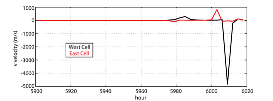
I deduced that I am getting large magnitude v velocities near my river sources. However, the velocities are occurring on what were previously (and still should be) land masked grid cells. I am defining my rivers as point sources using

#define UV_PSOURCE /*point sources*/
#define TS_PSOURCE /*point sources*/


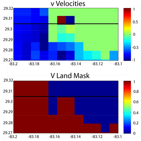
An example of the blowup is included in the attached image, where in the land cells adjacent to the river, two juxtaposed grid cells have v velocities of 30 m/s and -293 m/s.
Image

I have noticed that several other users have had problems with rivers in shallow water, but their concerns have been with large tracer values. Furthermore, since I have not activated any wetting / drying, I shouldn't be carrying velocities in land gird cells through time.

That all being said, I have a few speculations on what the issue could be, but your thoughts are of course welcome:

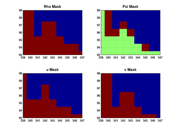
1. Is it possible that the v land mask is not being applied at the end of the integration?
2. Could the minimum depth (4m, 25 vert. layers) be too shallow?
3. Maybe I need to increase the height of the land from -1 m?


I should note that I ran the same month with point sources turned off (i.e. no rivers) and it does not blow up. I should also note that I am not using the most recent version of ROMS, instead I am working with version 240 (because it has already been downloaded and installed on our machine). I don't know if this is an issue that was addressed with the upgrade to version 3.3 or not.

Thanks for your help / thoughts in advance

Austin Todd

User avatar
drews
Posts: 35
Joined: Tue Jun 19, 2007 3:32 pm
Location: National Center for Atmospheric Research
Contact:

Re: Velocities in land grid cells

#2 Unread post by drews »

I had a problem similar to this one a few weeks ago with SVN revision 436. I got extreme velocities in the cell directly upstream of my river point source. Some differences:
1. I am using the 2-D barotropic mode (1 vertical level).
2. My grid resolution is 86m, 10x finer than yours.
3. I have wetdry turned on.
4. I #define UV_PSOURCE but not TS_PSOURCE.
5. My time step DT is 1 second, critical depth 0.1 m, depths about 3m.

The velocities in the offending cell were reasonable for a while, then they zoomed up into the 30 m/s range. My blowup problem stopped when I masked out the cell directly upstream from the point source. However, I set mask_rho and calculated the other masks from that.

1. What are your other mask values (mask_rho, mask_u, mask_psi) near the point source? Since this is a staggered grid, I wonder if you are not quite masking out the upstream grid cells completely?

2. Can you show us a plot of the velocities in the offending cells leading up to the blowup error?

Carl

austinctodd

Re: Velocities in land grid cells

#3 Unread post by austinctodd »

Thanks for the suggestion Carl...

After your response, I got to looking at my output in a bit more detail. It turns out that the velocities in these two cells pop up immediately (after the 1st time step). The velocities remain reasonable for a while, and stay steady around |1.2| m/s. This is still stronger than the transport I am prescribing for the river, but a reasonable value as far as ocean currents go. After about 9 months, the velocities start to diverge a little bit, and look as follows:

Image

Kind of a long time series, but you can see the how they really start to diverge around hour 5970. I'm suprised the model was still able to move forward after a velocity of nearly -5000 m/s was reached around hour 6010.

In regards to the grid masks, here is an image of the different masks for the same region where I am seeing these large velocities:

Image

I'll admit I am a bit ignorant when it comes to how all 4 masks work together, but I was under the impression that the v mask would be applied to the v velocities, and that's what would matter for the problem I am having. However, if you compare the image in my previous post with one just above (sorry about using lat/lon in that one and grid point # in this one), you'll notice that the large velocities occur in what are grid points (342,97) and (343,97). For the v mask, these are land cells. However, for the rho mask they are in fact ocean cells.

So, I guess my question now is... which grid should I be concerned with in terms of the masking? It seems since this is a v velocity, the v mask should be applied, and I shouldn't be seeing these large velocities. However, it appears that the rho mask may actually be the one that is applied here, allowing those velocities to persist.

Understanding the staggered grid seems to be key here. Does ROMS handle the transport coming out of point sources differently when masking (i.e. using rho mask instead of v mask)?

User avatar
kate
Posts: 4088
Joined: Wed Jul 02, 2003 5:29 pm
Location: CFOS/UAF, USA

Re: Velocities in land grid cells

#4 Unread post by kate »

Just so you don't confuse yourself, here are the numbers as ROMS would see them, assuming I have your mask right (land is green):
Image
Now, the way I would put a southbound river into this would be at i=342,343 and j=98. It may come up looking like it's at j=97 in the output file if you have a zero-based numbering on V-values. If your plotting code assumes all fields start at one, just shift everything in my plot by one.

Now, if there was no river, the point (342,98) would have a vmask of zero and that vmask would ensure that v there would always be zero. If there is a river, you are imposing a negative velocity there. The value of it is set by your river source and should always be imposed and not freely going nuts. Where exactly is your river source with respect to your land mask?

User avatar
drews
Posts: 35
Joined: Tue Jun 19, 2007 3:32 pm
Location: National Center for Atmospheric Research
Contact:

Re: Velocities in land grid cells

#5 Unread post by drews »

Here is the ubar current in my upstream grid cell (no masking):

Image

Those points are at 1-second intervals. This appears to be the same numerical problem, judging from your plot. If you can get your 4 masks to accurately represent the ROMS concept of "upstream cell", I think you'll mask out the problem. Maybe try using a single grid point for the source, temporarily, to keep things simple?

Carl

User avatar
drews
Posts: 35
Joined: Tue Jun 19, 2007 3:32 pm
Location: National Center for Atmospheric Research
Contact:

Re: Velocities in land grid cells

#6 Unread post by drews »

Here is a picture of the staggered grid from the ROMS wiki:

https://www.myroms.org/wiki/index.php/Grid_Generation

(I guess my initial 16 m/s current is _not_ "reasonable", but at least it doesn't blowup! :lol: )

austinctodd

Re: Velocities in land grid cells

#7 Unread post by austinctodd »

Thanks for your responses. I think I may have a problem with my masks in and of themselves. It appears from the diagram that Kate has drawn, that the v-grid should have one more entry than the rho grid in the j-direction, and that the u-grid should have one more entry in the i-direction than the rho grid. However, my grid sizes are as follows:

rho : 410x218
v : 410x217
u : 409x218

Should they be this instead?

rho : 410x218
v : 410x219
u : 411x218

The link that Carl posted from the ROMS wiki on Grid Generation seems to suggest this is the case.

These particular point sources are located at (342, 97) and (343,97), although that is referenced from zero. If my v-grid size is not correct, then this would likely explain why I am seeing velocities in these locations (should be shifted one down if there is an extra grid point).

austinctodd

Re: Velocities in land grid cells

#8 Unread post by austinctodd »

Sorry, but I managed to confuse my self quite a bit. My above comments on grid size are wrong. I see now that if my rho grid is dimensions (M x N), then my u grid must be (M-1 x N) and my v grid must be (M x N-1). This is evident from a previous post from the grid generation picture linked to above. I'm not sure what I was thinking.

Also, I just looked at my river forcing file again, and thought I should clarify. The (XI,ETA) positions I prescribe in my river forcing file for this particular river are (341,97) and (342,97). I read last numbers that I gave you off of my matlab plot :oops: .

If ROMS references from 0, then it seems the positions correctly corresponds to the locations I want. Is my logic here correct?


Thanks for your help, by the way!

User avatar
kate
Posts: 4088
Joined: Wed Jul 02, 2003 5:29 pm
Location: CFOS/UAF, USA

Re: Velocities in land grid cells

#9 Unread post by kate »

It's easy to confuse yourself with the plotting if the software doesn't know that we dimension things:

rmask(0:Lm+1,0:Mm+1)
umask(1:Lm+1,0:Mm+1)
vmask(0:Lm+1,1:Mm+1)

You can't tell from the NetCDF file what we think the starting index should be. Maybe this is a design flaw from more than twenty years ago, oh well. Still, we're consistent and the velocity flowing into box (i,j) from the north has to be specified as being at (i,j+1).

austinctodd

Re: Velocities in land grid cells

#10 Unread post by austinctodd »

Great. I think I finally have a decent understanding of how these masks work together. So, my question is now this...

Consider Kate's figure again (thanks for making this!)
If I had no rivers prescribed, my v mask at point v(i=342,j=98) and v(i=343,j=98) should be zero to prevent cross-boundary flow. However, I prescribe a southward-flowing river at this boundary... so should I in fact UNmask my v velocities at these points?

It seems maybe ROMS applies the vmask, then prescribes a UV point source AFTER applying the mask? I could understand how this might cause some instabilities. Otherwise, I would assume those cells should be explicitly zero after applying the mask.

User avatar
arango
Site Admin
Posts: 1350
Joined: Wed Feb 26, 2003 4:41 pm
Location: DMCS, Rutgers University
Contact:

Re: Velocities in land grid cells

#11 Unread post by arango »

One of the rules in Land/Sea masking is that we cannot have one-point, discrete bays. They need to be at least, two-points wide. If you have one-point bays, you cannot represent horizontal processes (advection, diffusion) with the current resolution. Therefore, you have two choices: (1) make them wider or (2) eliminate them.

This is a typical problem that user ignore when generating and fine tunning the land/sea mask with the editmask.m script.

austinctodd

Re: Velocities in land grid cells

#12 Unread post by austinctodd »

That is a very good point, Hernan. I will make sure my other river sources follow this rule.

In regards to the problem I've been having, though, I think I sorted out all of my masking issues, and decided instead to move to the code to see how my velocities at the river mouths are being computed, as they seemed ~3 times what I explicitly prescribe. I have found what seems to be a potential issue with the way point sources are handled using UV_PSOURCE.

Looking at step3d_uv.F, we see the section of code which says:

Code: Select all

# ifdef UV_PSOURCE
!
!-----------------------------------------------------------------------
! Apply mass point sources.
!-----------------------------------------------------------------------
!
      DO is=1,Nsrc
        i=Isrc(is)
        j=Jsrc(is)
        IF (((IstrR.le.i).and.(i.le.IendR)).and.                        &
     &      ((JstrR.le.j).and.(j.le.JendR))) THEN
          IF (INT(Dsrc(is)).eq.0) THEN
            DO k=1,N(ng)
              cff1=1.0_r8/(on_u(i,j)*                                   &
     &                     0.5_r8*(z_w(i-1,j,k)-z_w(i-1,j,k-1)+         &
     &                             z_w(i  ,j,k)-z_w(i  ,j,k-1)))
              u(i,j,k,nnew)=Qsrc(is,k)*cff1
            END DO
          ELSE
            DO k=1,N(ng)
              cff1=1.0_r8/(om_v(i,j)*                                   &
     &                     0.5_r8*(z_w(i,j-1,k)-z_w(i,j-1,k-1)+         &
     &                             z_w(i,j  ,k)-z_w(i,j  ,k-1)))
              v(i,j,k,nnew)=Qsrc(is,k)*cff1
            END DO
          END IF
        END IF
      END DO
# endif
However, I noticed that when this part of the code is run, it calculates the average layer thickness between cells [i,j] and [i-1,j] (u case) or between cells [i,j] and [i,j-1] (v case). However, there isn't a catch for the case that one of those cells is a land cell.

For my configuration, my minimum ocean depth is 4m and my land depth is -1m. Let's assume I have an even vertical grid stretching, 10 different layers, and a horizontal grid spacing of 500m. Then, between two cells with depth 4 meters, my average layer thickness in each layer should be 0.4m. However, if I take the average between a cell that has 4m depth and a cell that has depth -1m, my average layer thickness is 0.5*(0.4m + 0.1m) = 0.25m. I don't know that the layer thickness actually works with a negative depth, but take it for argument's sake...

Now if I then prescribed my transport to be 50 m^3/s the first case of two equal depth cells would give me a velocity of (50 m^3/s) / (0.4m*500m) = 0.25 m/s. However, the latter case would give velocities in each layer of (50 m^3/s) / (0.25m*500m) = 0.4 m/s ... almost double. This seems relatively consistent with difference in speeds that I've been seeing.

So, do I
1) Apply a catch in step3d_uv.F to correct for cases when I am at a land boundary?
2) Change my land depths from -1 to -4 (same magnitude as min. ocean depth)?
3) Add one ocean cell upstream from my point source (does not seem like the right thing to do to)?

or, have I missed something completely with the way the code works here?

User avatar
kate
Posts: 4088
Joined: Wed Jul 02, 2003 5:29 pm
Location: CFOS/UAF, USA

Re: Velocities in land grid cells

#13 Unread post by kate »

The water depth at v points is assumed to be an average of the depths at the two neighboring cells. This is the way these discrete operators work. Perhaps you are getting the correct velocity after all if you change your expectations.
2) Change my land depths from -1 to -4 (same magnitude as min. ocean depth)?
You really, really don't want to do this. Then you'll have zero right at the wall. Bad idea.

austinctodd

Re: Velocities in land grid cells

#14 Unread post by austinctodd »

I agree with you, Kate. I definitely do not want to do this. I should be more clear with my problem.

It lies in exactly what you said:
The water depth at v points is assumed to be an average of the depths at the two neighboring cells
This is physically a problem if one of the neighboring cells is a land cell :!: For land cells, we take a negative depth (i.e. my -1m above). So, taking the average of 4m with -1m gives an average depth of 1.5m. This is exactly what this is happening with the code written as

Code: Select all

DO k=1,N(ng)
   cff1=1.0_r8/(om_v(i,j)*                           &
&       0.5_r8*(z_w(i,j-1,k)-z_w(i,j-1,k-1)+         &
&               z_w(i,j  ,k)-z_w(i,j  ,k-1)))
   v(i,j,k,nnew)=Qsrc(is,k)*cff1
END DO
This was a particular problem for me, because I had a tropical storm enter my domain, increasing winds in the same direction as river flow, and dropping the sea surface height above these particular cells to -1.4m. That means when all ~100 m^3/s were being pushed through ~10cm of water.

So, my #2 suggestion is clearly wrong (for some reason at the time I guess I had thought the depth of land was being taken as absolute value). For people with deeper rivers, I could see how they might not have their their velocities affected as significantly as mine are. Although, I am not sure what you mean when you say
Perhaps you are getting the correct velocity after all if you change your expectations.
It seems the suggestion
1) Apply a catch in step3d_uv.F to correct for cases when I am at a land boundary?
is what is needed. If the depth at either point is < 0 (or masked by a land mask), then the code needs to take only the layer thicknesses of the cell in which I am putting a flux into.

User avatar
kate
Posts: 4088
Joined: Wed Jul 02, 2003 5:29 pm
Location: CFOS/UAF, USA

Re: Velocities in land grid cells

#15 Unread post by kate »

I have the depth of my land points at the same depth as the shallowest water points, in your case 4 m instead of -4 m.

The value shouldn't get into any other computations, so it shouldn't matter what you pick as long as it isn't zero. If you are using WET_DRY, then that's a more complicated story.

austinctodd

Re: Velocities in land grid cells

#16 Unread post by austinctodd »

Ok, well this makes much more sense then. I essentially did the same thing for a test case. However, I only made the cells upstream of my point sources the same depth as my minimum ocean depth (all other land points have a depth of -1m). For this case, the model ran smoothly through my previous trouble point, and the velocities also look much closer to those that I prescribe. :D

I suppose since we have the mask over everything that is considered to be land anyways, it makes more sense to just make all land cells the same depth as the minimum ocean depth (and yes, for the case without wetting and drying).

I didn't know this was the recommended way to handle the depth of land cells. I had just assumed that since it was land, its depth must be the opposite sign of the ocean cell depths.

Thanks again for your help.

Austin

Post Reply